How QR Code Scanning Works: 8-Stage Pipeline Explained
Image capture, binarization, finder patterns, Reed-Solomon correction — every step to decode a QR code in under a second, explained with diagrams.
This article was written by the QR Nova team. We build QR code software, which may inform our perspective.
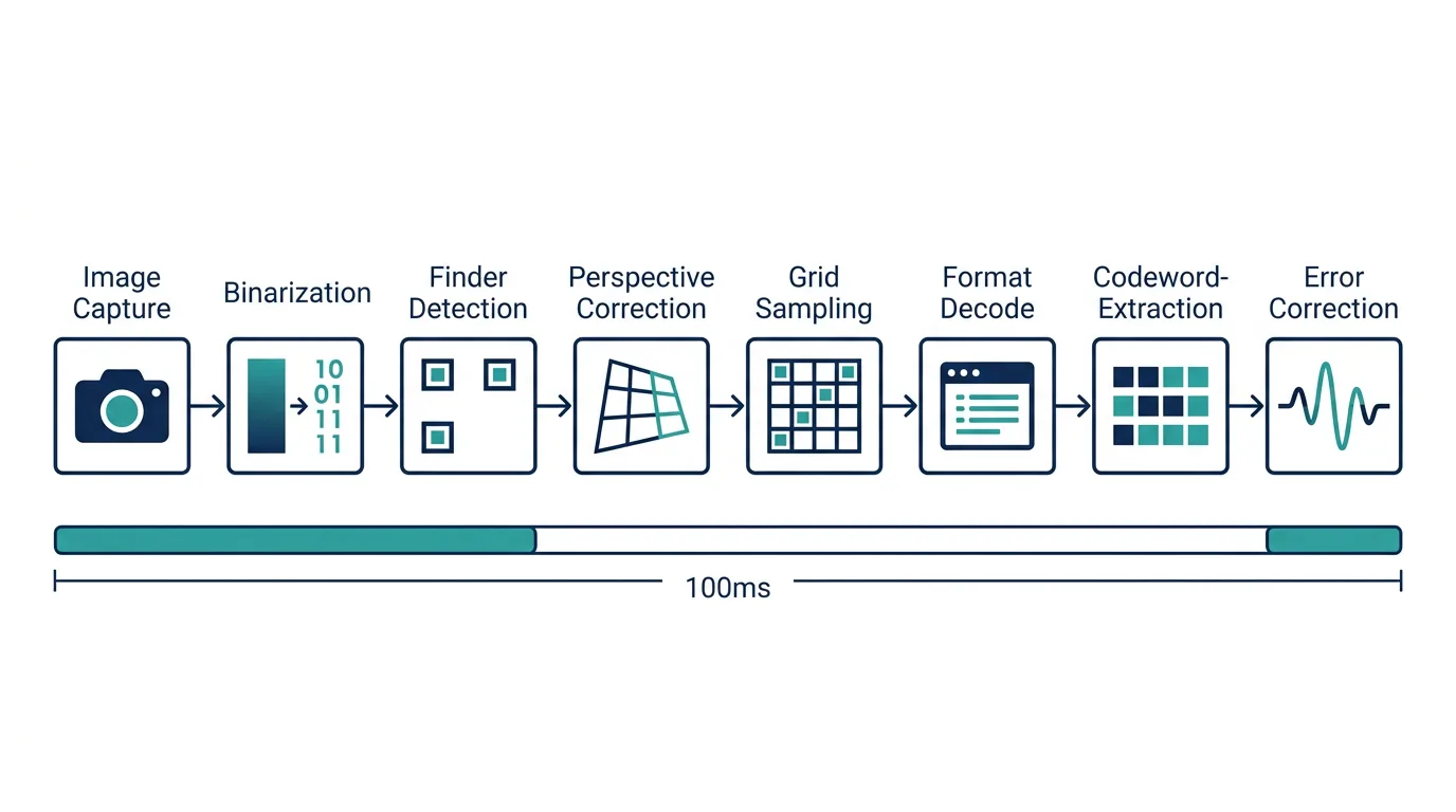
Your phone decodes a QR code in under 100 milliseconds. In that time, it captures a video frame, converts a gradient photograph into a binary grid, locates three corner targets using a ratio that holds at any angle, corrects for perspective distortion, samples 441 to 31,329 individual cells, runs polynomial arithmetic over a finite field to recover corrupted bytes, and delivers a URL or text string. All before you've consciously registered that you pointed the camera. Most explainers stop at "your phone reads the pattern." This one walks through every step of how QR code scanning works technically, from raw photons to decoded payload, following the pipeline defined in ISO/IEC 18004.
TL;DR
- The pipeline has eight distinct stages: image capture, binarization, finder pattern detection, perspective correction, grid sampling, format decoding, data extraction, and Reed-Solomon error correction.
- Finder patterns, the three corner squares, are what make QR codes scannable at angles. Their 1:1:3:1:1 ratio is the key.
- Reed-Solomon error correction works by treating data as a polynomial over GF(256). At level H, up to 30% of codewords can be corrupted and fully recovered.
- Contrast failures and missing quiet zones are the two most common physical causes of scan failure, both affect stages that run before error correction can help.
- The actual computation takes under 30ms. The delay you perceive is your camera's autofocus, not the decoder.
Stage 1: image capture and binarization
Generate your first QR code — free
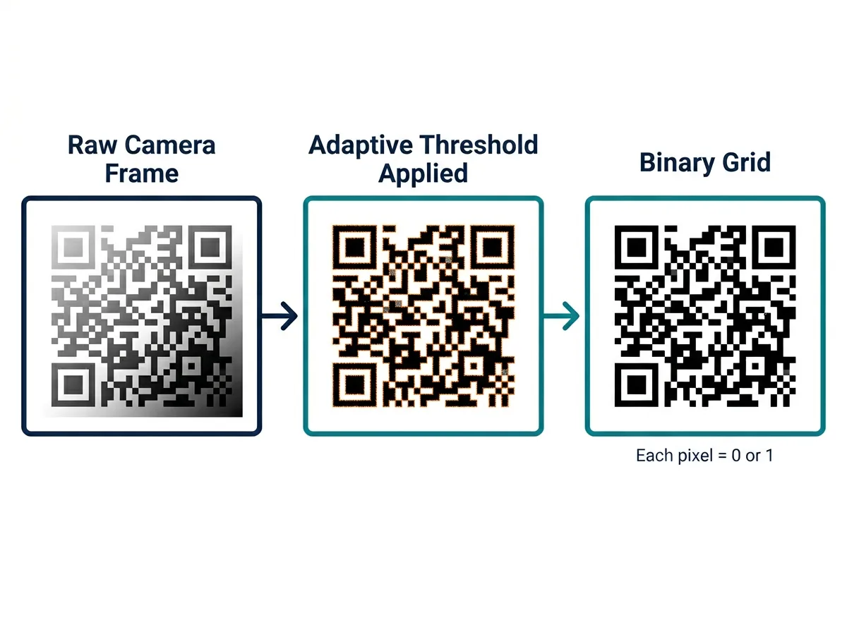
Get startedA phone camera does not see black and white modules. It captures a continuous luminance gradient: JPEG or raw frame data where each pixel has a value from 0 to 255. The decoder's first job is converting that grayscale image into a true binary image. Every pixel becomes either 0 (dark module) or 1 (light module). No in-between.
The naive approach is to pick a global threshold of 128 and call everything darker "black." This falls apart the moment a QR code is printed on a slightly reflective surface, scanned in uneven light, or placed near a bright window. The part of the code in shadow might average around 60 while the lit part averages around 180; a single global threshold misclassifies one of them.
Production decoders use adaptive (local) thresholding instead. The image is divided into a grid of small tiles (ZXing uses a block size of roughly 1/8 of the image width). For each tile, a local threshold is computed from the luminance histogram of just that region. A pixel counts as dark if its value falls far enough below the local mean, typically by a delta of 5 to 10. So a shadow over the top-left corner of the code does not affect the threshold applied to the bottom-right.
What comes out is a binary bitmap where each cell of the QR code is represented as solid black or solid white, assuming the original contrast was adequate. This is why contrast is not a cosmetic concern. Low contrast produces ambiguous pixel values that adaptive thresholding cannot reliably classify. A dark navy QR code on a dark gray background? Dead at stage 1, before any other step runs.
Stage 2: finding the finder patterns
With a binary image ready, the decoder needs to locate the QR code within it. The anchors are the three finder patterns: the large concentric squares sitting in the top-left, top-right, and bottom-left corners of every QR code.
Each finder pattern has a specific structure: a 3x3 dark center square, surrounded by a 1-module-wide light border, surrounded by a 1-module-wide dark border. Scan any horizontal or vertical line through the center and the run-length sequence of dark and light pixels produces the ratio 1:1:3:1:1. One dark, one light, three dark, one light, one dark.
The decoder exploits this by scanning every row of the binary image left to right, counting runs of same-colored pixels. Every time five consecutive runs appear, it checks whether their lengths satisfy the 1:1:3:1:1 ratio (within a tolerance of about 0.5x). Candidate center points get logged. Then the same scan runs vertically through each candidate's column, confirming the ratio holds in both directions. Where horizontal and vertical confirmations intersect, you have a high-confidence finder pattern center.
Here's what makes this clever: the ratio is invariant to scale and rotation. Whether the QR code is 50 pixels wide or 500, whether it's rotated 45 degrees, the ratio holds. The finder pattern geometry encodes orientation, not the data modules. Locate three of them, and you immediately know the code's position, scale, and rotation in the image.
The quiet zone (the mandatory 4-module white border around the code) exists to serve this step. Without it, the 1:1:3:1:1 scan generates false positives from dark background elements adjacent to the finder pattern, or the bounding box calculation for the code's extent gets thrown off. Missing quiet zones are one of the most common sources of intermittent scan failures on codes that look perfectly fine to the naked eye.
Stage 3: perspective correction
Cameras rarely face a QR code head-on. The code is tilted, skewed, or photographed from an angle that makes a square pattern appear as a trapezoid. Reading module positions from a distorted image produces wrong values, so the decoder reverses the distortion first.
With the centers of the three finder patterns known, plus the alignment pattern (present in versions 2+) or the inferred fourth corner, the decoder has four known points in the distorted image that correspond to four known positions in an ideal, head-on grid. Classic homography problem: find the 3x3 perspective transformation matrix that maps the distorted coordinates to the canonical grid.
The homography is computed using direct linear transform (DLT) or a similar solver. Once known, every module center's canonical position maps back to a pixel coordinate in the original image, telling the decoder exactly which pixel to sample for each grid cell. Most implementations do this lazily: compute the transform once, then sample each module on demand rather than warping the entire image.
For higher-version QR codes (version 7 and above, which can have dense data regions that cover a large physical area), local perspective drift across the code area becomes significant. Alignment patterns, small concentric squares embedded in the data area at regular intervals, serve as additional calibration anchors. The decoder samples alignment pattern centers and uses them to refine the perspective model locally, dividing the code into smaller regions each with their own corrected sampling grid.
Stage 4: sampling the grid
After perspective correction, the decoder knows where every module center sits in the original image. Sampling is straightforward: for each cell in the QR code grid, read the pixel value at the mapped coordinate and threshold it to black or white.
One thing worth understanding: this sampling reuses the adaptive threshold already computed for that region of the image, not a fresh global threshold. The decoder has been working in binary space since step one. It's just now retrieving values at specific coordinates.
The result is a 2D boolean grid, an NxN matrix of dark and light values where N ranges from 21 (version 1) to 177 (version 40). Most of it is data, but certain regions have fixed meanings: the finder patterns themselves, timing patterns (alternating black-white strips that calibrate the grid spacing), the dark module (always dark at a fixed position), and alignment patterns. The decoder masks these structural areas out and focuses on everything else.
Stage 5: reading format and version information
Before extracting any data, the decoder needs two pieces of structural metadata: the format information and, for version 7+ codes, the version information.
Format information lives in two identical copies at fixed positions adjacent to the finder patterns. It encodes 15 bits: 2 for the error correction level (L, M, Q, or H), 3 for the data mask pattern, and 10 BCH error-correction bits that protect the format information itself against up to 3 bit errors. These bits are XORed with a fixed mask pattern (101010000010010) before storage so they're never all-zero, even for unfavorable combinations.
The mask pattern is critical. Raw QR data often has long runs of same-colored modules, and the binarization step misreads those as boundary artifacts. During encoding, one of eight predefined XOR mask patterns is applied to the data modules to break up such runs. The encoder evaluates all eight masks and picks the one that produces the most balanced, high-contrast pattern by a penalty score. Without knowing which mask was applied, the decoder cannot undo it, and the data bits are gibberish.
Getting format information wrong is fatal. Both copies corrupted beyond BCH correction capacity? The decoder cannot determine the mask pattern and cannot unscramble anything. A sticker or scratch covering the corner adjacent to a finder pattern is far more damaging than equivalent destruction anywhere else on the code.
Stage 6: extracting the data codewords
With the mask known, the decoder XORs it back over the data region, restoring the original encoded bits. Data is read in a specific zigzag order: starting from the bottom-right corner, two columns at a time, reading upward then downward in an alternating serpentine path, skipping fixed structural regions. Every data module is visited exactly once.
The bit stream gets grouped into 8-bit codewords. The first few bits specify the encoding mode: numeric (10 bits per three digits), alphanumeric (11 bits per two characters), byte (8 bits per character), or Kanji (13 bits per character). A character count field follows, then the encoded data, a terminator sequence, and padding to fill the remaining capacity.
After the data codewords come the error correction codewords, computed during encoding by Reed-Solomon and appended in defined blocks. The next stage uses these to verify and repair the data.
Stage 7: reed-solomon error correction
This is the step that makes QR codes survive physical damage. It requires a bit of finite field arithmetic, but the concept is accessible without full proofs.
The finite field foundation
Reed-Solomon operates over GF(256), a Galois Field with 256 elements. Think of it as a number system where every value is a single byte (0-255), but the arithmetic rules differ from ordinary integer math. Addition is just XOR. No carries, fully reversible. Multiplication is defined by a primitive polynomial; in QR codes, the field uses x^8 + x^4 + x^3 + x^2 + 1. Every non-zero element of GF(256) can be expressed as a power of a primitive root alpha, which simplifies multiplication to exponent addition modulo 255.
Why bother with a finite field? In ordinary arithmetic, dividing polynomials produces fractions. Over a finite field, every non-zero element has a multiplicative inverse, so polynomial division always yields exact quotients and remainders within the field. That property is what makes the entire error correction scheme work.
Encoding: appending check bytes
During QR code creation, the data bytes are treated as coefficients of a polynomial D(x). Multiply by x^r (shifting left by r positions, where r is the number of error correction codewords), then divide by a generator polynomial G(x) using polynomial long division over GF(256). The remainder of that division, r bytes, gets appended to the data as the error correction codewords.
The generator polynomial for r check bytes is the product of r linear factors: G(x) = (x - alpha^0)(x - alpha^1)...(x - alpha^(r-1)) where alpha is the primitive element of GF(256). For QR level H with 28 error correction codewords per block, G(x) has 28 roots.
Decoding: computing syndromes
On your phone, the decoder treats the received codeword sequence (data plus error correction bytes) as a polynomial R(x). If nothing went wrong, R(x) divides evenly by G(x) and the remainder is zero. If errors crept in, R(x) = C(x) + E(x) where C(x) is the correct codeword polynomial and E(x) is an error polynomial with non-zero coefficients at the corrupted positions.
The decoder evaluates R(x) at each of the r generator roots: S_i = R(alpha^i) for i from 0 to r-1. These r values are the syndromes. All zeros means a clean message. Any non-zero syndrome means errors are present.
Locating and correcting errors
Given the syndrome values, the decoder runs the Berlekamp-Massey algorithm to find the error locator polynomial, whose roots correspond to the positions of the corrupted bytes. Finding those roots (by evaluating the polynomial at all 255 non-zero field elements, a process called Chien search) gives the error locations. Then the Forney algorithm computes error magnitudes at each location: how much to XOR each corrupted byte to restore the correct value.
For erasures (positions where the decoder knows a byte is unreliable, like a module that fell below a confidence threshold during sampling), the correction capacity doubles. A code with r check bytes corrects t errors where t = r/2. If k erasure positions are already known, it handles up to r - k additional unknown errors on top of that. QR level H with 28 check bytes per block corrects 14 unknown errors or 28 known erasures per block, or any combination in between.
What this means practically
A version 1-Q QR code has 13 data codewords and 13 error correction codewords per block. Destroy 6 of those data codewords completely (a scratch that obliterates roughly 46% of the data region) and all 13 original bytes are still recoverable. This is why logos embedded in QR codes work: the central modules are intentionally corrupted, and error correction absorbs the loss.
The limit is real, though. Exceed the correction capacity and the decoder either silently produces a wrong output (rare, because the final check catches most failures) or returns nothing. Production decoders handle edge cases by checking both format information copies and retrying with slightly varied thresholds. ZXing, for example, retries with progressively coarser binarization parameters before giving up.
Stage 8: reassembling the message
After Reed-Solomon, the decoder has a verified byte sequence. The final step unpacks it according to the mode and character count fields read in stage 6.
For byte mode (the most common for URLs), each 8-bit codeword maps directly to a Latin-1 or UTF-8 byte. Read the character count, take that many bytes from the payload, produce the final string. Numeric mode maps groups of 10 bits to three-digit decimal numbers; alphanumeric mode maps 11-bit groups to two-character pairs from a 45-character alphabet. You can even concatenate multiple segments with different modes in a single QR code. A URL with only alphanumeric characters followed by a binary payload is perfectly valid.
The output string is what your phone shows you: a URL, a phone number, a plain text message, a Wi-Fi credential block. At this point the scanner's job is done and the OS takes over. Follow the URL, dial the number, prompt for Wi-Fi connection.
Why the pipeline design matters for code quality
Knowing the pipeline changes how you should think about QR code design. Each stage has practical consequences.
- Binarization means contrast ratio is not optional. You need at least a 40% luminance difference between module and background for reliable scanning across devices. Dark-on-dark or light-on-light codes fail at stage 1 regardless of error correction level.
- Finder pattern detection means quiet zones are structural, not cosmetic. Codes that bleed to the edge of a printed area with no margin fail at stage 2.
- Format information sensitivity means the corners adjacent to finder patterns must be protected from damage and obstruction. Even level H error correction cannot help here, because format info is decoded before the error correction level is known.
- Reed-Solomon capacity means damage tolerance is predictable and quantifiable. For a code displayed outdoors or printed in a high-wear environment, choosing level Q or H and sizing generously gives real resilience, not a vague promise that "QR codes handle damage."
QR Nova's generator lets you set the error correction level before creating a code, because the right choice depends entirely on where the code will live. A screen-displayed code in a controlled environment is fine at level M. A vinyl sticker expected to last three years on outdoor equipment warrants level H, even at the cost of a denser, higher-version code.
The actual speed breakdown
On current smartphone hardware (tested on 2024-2025 iOS and Android flagships), here's how the decode pipeline breaks down per video frame:
- Grayscale conversion and binarization: 2-5ms (SIMD-optimized in native libraries)
- Finder pattern scan: 3-8ms (linear in image height)
- Perspective correction and grid sampling: 1-3ms
- Format decode + Reed-Solomon: under 1ms for version 1-10 codes
Total pipeline: well under 30ms on a single frame. At 30fps the decoder gets 33ms per frame; at 60fps, 16ms. Either way, computation is not the bottleneck. That 0.5 to 2 seconds you experience when scanning is almost entirely optical: autofocus settling, motion blur from an unsteady hand, and the time the code spends partially outside the frame before you center it.
This also explains something that annoys people: scanning a QR code on a screen is sometimes harder than scanning a printed one. Screens at high brightness introduce glare that the binarization step treats as a light halo around dark modules, shrinking the effective module size below what the grid sampler expects. Slightly reducing screen brightness when displaying a QR code is not superstition. It removes a genuine binarization artifact.
Conclusion
That hundred-millisecond decode is eight distinct computational stages working in sequence, each dependent on the one before it. Binarization converts optics to data. Finder patterns provide orientation invariance. Perspective correction maps a distorted real-world capture to a canonical grid. Format information unlocks the mask. Reed-Solomon arithmetic over GF(256) recovers corrupted bytes with mathematical certainty, up to a defined limit.
Once you understand the pipeline, QR code failures stop being mysterious. A code that scans inconsistently is almost never "broken." It's hitting a specific stage boundary: contrast too low for binarization, quiet zone too narrow for finder detection, format region damaged before error correction can engage. Diagnose the stage and you diagnose the fix.
If you're generating codes for production use, match the error correction level to where the code will live, keep the quiet zone intact, and verify contrast programmatically, not just by eyeballing it. The math handles the rest.
Frequently asked questions
How does QR code scanning work technically, step by step?
QR code scanning works technically through eight stages: the reader captures an image, converts it to black-and-white through adaptive thresholding, locates the three finder patterns in the corners, corrects for perspective distortion using a homography transform, samples each module in the grid, reads format information to determine error correction level and mask pattern, extracts the encoded codewords, and then runs Reed-Solomon error correction to recover any corrupted bytes before finally decoding the data payload into text or a URL.
What are finder patterns in a QR code and why do they matter?
Finder patterns are the three large square targets in the top-left, top-right, and bottom-left corners of every QR code. Each has a 1:1:3:1:1 dark-to-light ratio across any scan line through its center. Because this ratio is invariant regardless of scale or rotation, a decoder can locate and orient a QR code even when the camera is at a sharp angle or the code is partially outside the frame. Without finder patterns, the decoder would have no reliable anchor to establish the code's position and orientation.
What is Reed-Solomon error correction and how does it work in QR codes?
Reed-Solomon error correction treats the data bytes as a polynomial and appends additional check bytes computed by dividing that polynomial by a generator polynomial over a Galois Field (GF(256)). During decoding, the receiver recomputes the same division. Any non-zero remainder reveals that errors are present; the syndrome values then let the decoder locate which bytes are wrong and compute the correct values, up to the code's correction capacity. In QR codes at level H, up to 30% of codewords can be corrupted and fully recovered.
Why does QR code contrast matter for scanning?
The binarization step that converts a camera image to black-and-white modules relies on detecting a clear luminance boundary between dark and light cells. When contrast is low, for example, dark gray on black, or light yellow on white, the adaptive threshold algorithm may flip modules to the wrong value. A single wrong module in a data region costs one codeword; a wrong module in the format information region can cause the entire decode attempt to fail before error correction even runs, because the decoder needs format info to know the mask pattern.
Can a damaged QR code still be scanned?
Yes, up to the limit of the error correction level used. Level L corrects up to 7% of codewords, level M up to 15%, level Q up to 25%, and level H up to 30%. Physical damage, ink smear, or partial occlusion that corrupts codewords within those limits is fully recoverable. The catch is that all format information blocks must still be readable, because the decoder uses format info to determine the error correction level and unmasking key before it can even attempt data recovery.
How fast does QR code scanning actually happen?
On a modern phone at 60fps, the full pipeline, binarization, finder pattern search, perspective correction, grid sampling, format decoding, Reed-Solomon, and final decode, runs in under 30ms on a single video frame when the code is reasonably well-framed and lit. The apparent delay users experience is almost always the autofocus settling, not the decoding computation. Libraries like ZXing and ZBar are highly optimized; the bottleneck is optical, not algorithmic.
What is the quiet zone in a QR code and why does it matter?
The quiet zone is the mandatory blank margin of at least four modules surrounding all four sides of a QR code. The finder pattern detection algorithm works by scanning for the 1:1:3:1:1 ratio; without the quiet zone, a dark background can produce false-positive ratio matches adjacent to the real finder patterns, or cause the bounding-box calculation to miscalculate the code's extent. A missing quiet zone is one of the most common causes of intermittent scan failures on otherwise well-designed codes.
Related articles
QR Code Error Correction Levels: The Reed-Solomon Math
QR code error correction levels (L, M, Q, H) explained with the real Reed-Solomon math, version trade-offs, and damage-test data. Generate yours free.
How Dynamic QR Code Redirects Work: Technical Deep Dive
Scan to destination in under 300ms. The full redirect chain: edge routing, caching, failover, and why vendor lock-in is a real risk — with latency benchmarks.
ISO 18004: The QR Code Standard Explained
ISO 18004 is the spec every QR code follows. Learn what it defines: structure, encoding modes, error correction, and the version system, explained plainly.
Generate your first QR code — free
Get started